Musical Meddling
| Musical Meddling: A Single-Pole Passive Filter For Beautiful Biamping |
| Commentary |
| Greg Weaver |
| 25 December 2000 |
A Reason to Meddle
It had been a night of live blues at a little club downtown. Afterward some of us had gone back to my place and lit up the system with some vintage Chicago blues. Suddenly, Pete asks, “Can you turn it up?” Unfortunately, I had to admit that we were just about at the dynamic limits of the superb little Pass Labs Aleph 3. Though rated at only 30 watts per channel, when paired with my Von Schweikert Research VR 4 Generation II’s, with their relatively high 91 dB/W efficiency, they have no problem filling my 15.5’ × 23’ room – within reason. With the impetus of that seemingly innocent question I knew it was time to meddle! After a few quick e-mails to Albert Von Schweikert, designer of my speakers, and HAL, my engineering audiophile buddy, I was ready to rock!
Last spring, HAL had alerted me to the deep discounts being offered on the Hafler Trans-Nova series of amplifiers by HCM Audio Online. Why were these Hafler amps so attractive for my project? Let me count the ways. They have excellent overall sonic performance for their price, especially in the low frequencies, which was an important consideration. They had their own front-panel-mounted volume controls, also critical for our project. Finally, they are quite affordable, especially the B-stock units.
What is a B-stock amplifier, you ask? Simple. Typically, it is a unit that failed in the field, was replaced under warranty and came back to the shop for repair. Once fully repaired to factory specification, because they frequently show some small signs of use, they cannot be resold as new. As B-stock units, they are electronically perfect and carry a full warranty. All the performance at something like 50% of the retail price—what’s not to like? The B-stock 75 watt-per-channel P1500 Trans-Nova I selected, which retails for $599, was just $300.
Now, you certainly don’t have to buy a new amp if you happen to have a suitable one lying around. When using two identical amps, you would likely opt for what is known as a Vertical Biamp configuration. In this application, aside from maximizing channel-to-channel separation, you would also negate any problems with input to output impedances, level matching, and so on.
Here we will be addressing the more common biamplification configuration, using one amp for bass reproduction and yet another for the high frequencies. In this configuration, you will want to use at least one amplifier with output controls, preferably the low frequency amp. Independent volume control for at least one amp is crucial, because without it you will have no chance of matching the outputs to balance the performance. It will also be important for the amp used for bass reproduction to have more gain than the one you will be using for the higher frequencies. If you’ve got a suitable amp lurking about, or know an audio bud that has some extra power packed away in storage, you are ready to move.
What’s What, and Why
Let’s take a look at the spectrum of human hearing. It is accepted that we are capable of hearing from 20 Hz to 20 kHz. If we start at 20 Hz and break this audible spectrum into musical octaves, we get the following results.
20 Hz to 40 Hz – Octave one
41 Hz to 80 Hz – Octave two
81 Hz to 160 Hz – Octave three
161 Hz to 320 Hz – Octave four
321 Hz to 640 Hz – Octave five
641 Hz to 1,280 Hz – Octave six
1,281 Hz to 2,560 Hz – Octave seven
2,561 Hz to 5,120 Hz – Octave eight
5,121 Hz to 10,240 Hz – Octave nine
10,241 Hz to 20,480 Hz – Octave ten
It is significant to note that EACH octave requires the SAME acoustical power as any other. This means that it takes the same percentage of the amplifier’s available power to play the 10,240 cycles between 10,241 Hz and 20,480 Hz (the top octave), as it does the 20 cycles from 20 Hz to 40 Hz (the bottom octave). Mathematically, this is expressed as a logarithmic relationship. What does all this mean? Let’s say we are listening to a symphonic work and we are pleasantly cruising along to the delicate sound of a triangle using 5 watts of available amplifier power.
Now a bass drum kick hits. You suddenly need ten times that 5 watts of coasting power, or 50 watts, to recreate that bass drum whack at the same volume that you hear the struck triangle! If we are using a 7-watt SET Triode, or other similarly low-power amplifier being played at a realistic volume, it is easy to see that the sudden demand for power to recreate this bass note will distort the output signal significantly. This resultant form of distortion here is known as clipping, because it “clips” off the top and bottom of the waveform. If, on the other hand, we are using a 100-watt amplifier, we still have power to spare!
Although you can biamplify without the use of a crossover filter like the one under discussion here, you will gain several significant advantages by doing so. Without such a filter in place, both amplifiers are reproducing the full spectrum of frequencies, 20 Hz to 20 kHz. By relying ONLY on the speaker’s internal crossovers to filter unwanted information away from the respective drivers, we are simply expending the unused power through the crossover. Though this works just fine, it is a tremendous waste of amplifier power!
Let’s take a look at a graphic example. If the speaker system we wish to biamplify will be crossed over at a 640 Hz (not too likely, but selected for its clarity in this example), then without the use of such a filter, each amplifier will be generating the entire audible frequency spectrum. Now, because of the way the drivers in our model use this power, with only one half of the spectrum needed for the low frequencies and the other half necessary for the highs, each amplifier would be WASTING fully one half of its acoustic power. What if we were to ask the amplifiers in question to ONLY amplify the portion of the signal their respective driver complement will be reproducing? See where we are headed?
If we employ a high-quality crossover filter before the two amplifiers, with the intent being the relief of the physical duty of reproducing any frequencies other than their respective driver compliments will be responsible for, we achieve two very substantial results. We have considerably more effective use of the absolute power available to us and we have significantly reduced the demand on each, thereby enhancing their respective sonic capabilities.
Let’s take a more realistic model like my own speakers that cross over at 120 Hz between the woofer section and the mid/tweeter module. If, through implementing ahigh-pass filter, we eliminate the need for the high-frequency amplifier to reproduce the bottom 2½ musical octaves (from 20 Hz up to 120 Hz), we have freed it of 25% of its most demanding workload! Since low-frequency reproduction places the most severe load on an amplifier, extracting the most current, it puts a substantial drain on the power supply. Relieving the high-frequency amplifier of this stressful duty results in wonderful sonic benefits, such as greater ease, detail, and clarity. Win/Win, eh?
Now let’s take a look at the other side of the coin. What advantages are gained by reducing the duties of the low-frequency amp with the application of the 120 Hz low-pass filter. Our low-pass filter prevents the top seven and a half octaves (121 Hz to 20,480 Hz) from ever reaching the low-frequency amp; that is 75% of the previous full-frequency load! We can now devote all this newfound power to the accurate and powerful recreation of ONLY the bottom 2½ octaves. I hate to repeat myself, but clearly a Win/Win circumstance once again.
Number Crunching
Between Albert and HAL, I got all the science and assistance I needed. Our filter of choice is a shallow-slope single-pole 6 dB per octave type of filter for both high- and low-pass branches. By definition we have a Butterworth or Linkwitz-Reilly alignment filter in this case. Why single-pole? Well, most would agree that it is the least invasive on the signal, creating the lowest level of phase shift and degradation on the low-level signal coursing through it. The equation for finding the -3 dB point for our crossover is:
F-3 dB = 1 / (2 x PI x R x C)
Where:
F-3 dB is the -3 dB point of the circuit filter point in Hz.
R is the total series or parallel resistance used in ohms.
C is the capacitance in Farads.
Notice that in the Resistance branch of the equation that I said total series or parallel resistance. If the preamp has a relatively high output impedance (>100 ohms) and the series resistance is low (<1000 ohms) for the high-pass filter branch, the -3 dB point will be off the calculated value. You can correct for this by includingthe output impedance of your preamp (check your owners manual). Similarly, for the high-pass function, you can just use the input impedance of the amp, measured in ohms, for R.
It is a little more difficult to calculate the low-pass value since you have both attenuation and filter roll off to work with. You can add the series R and then parallel the input impedance with the C. This is essentially a shelf filter since it drops the entire band of operation. Keep in mind that output impedance comes into play as level offset in the low-pass filter. If you add a series resistor in the low-pass section, then the impedance is the sum of the series resistor and the input impedance of the amp. It is not totally resistive, but close enough for our purposes.
This is one reason why you will want to have more gain in the bass amp than the treble amp. Matching levels will be very tough to do unless you actively buffer the low-pass filter output before the amp input (way beyond the scope of this do-it-yourself [DIY] article), or have level controls in one or both amps. See—I said it was crucial to our project.
My chosen flex point was 120 Hz, because that is crossover point between the bass and midrange/high-frequency modules in my Von Schweikert VR 4 Gen II’s. This value, computed for my equipment, yields approximately 0.47 micro Farads for the capacitance and about 2.2 k-ohms for the resistance.
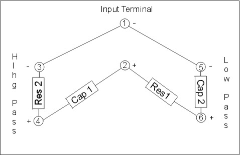
Okay, so now that we have the theory out of the way, let’s have some fun and get down to building stuff, shall we? We want to build the following circuit.
Getting the Goods
I spent just over 1½ hours assembling the boxes and another half hour doing the final balancing. If you are not a seasoned solder sniffer, you may need 4 to 5 hours for all of this, so slate your time accordingly if you have other obligations, okay?
For this project you will need a good soldering iron, a drill, several drill bits (one ¼” and one smaller pilot bit), diagonal cutters, a set of needle nose pliers, some good solder, and about a foot or so of high quality hook-up wire. I used some Harmonic Technology Single CrystalTM 22-gauge silver wire that I had on hand. You can opt for any high-quality type of wire. You will also need a Volt/Ohm meter and a Radio Shack (or similar) Decibel meter. Beside a second amp, you will also need two more sets of RCA-type interconnect cables. Use the best ones you can afford. Our raw components will be acquired from two places, Radio Shack and The Parts Express—the hobbyist friendly division of Sonic Frontiers.
At the Shack, you will want to pick up two black plastic experimenter’s boxes and three sets of gold-plated, chassis-mount phono jacks. The “Project Enclosures” I used, part number 270-1801, are a scant 3″ x 2″ x 1″. Given the size of the capacitors I chose, this makes for a pretty tight fit. If you are NOT an experienced DIY’er, opt for a larger pair of experiment boxes. Trust me, the small boxes force a snug but cozy fit that might frustrate all but the most experienced and patient solder hounds. If you opt for the larger boxes, plan to double the amount of hook-up wire you will use, as you will likely need to extend the capacitor and resistor leads, as well as make the ground-leg connections.
You may wonder why I am using the inexpensive Radio Shack jacks rather than some of the more expensive “audiophile-approved” versions that are available. Quite simply, I vastly prefer the lowest mass, least complex plating scheme I can find. These fill the bill perfectly and have been my choice for such projects for some time. Feel free to use larger, sturdier, and more expensive jacks. If you do, don’t use the small project enclosure; you won’t have a chance of cramming everything in. Oh yes, and don’t blame me for the excessive signal attenuation.
For the actual electronic components, point your browser to The Parts Connectionand look at the online catalog with the Adobe Acrobat Viewer (available free atwww.adobe.com). Make your parts selection, or, if you are using the same crossover point as me, you can just call 1-800-769-0747 and fire off your order. If you have VSR VR models (that includes the 4, the 4 Gen. II, the 4.5, the 6 and the 8), you’ll be happy to know that this is an Albert-approved project!
As the drawing indicates, we will need four of each part, one set to be used in each branch of our circuit, with two complete units necessary for stereo. First, I used 4 InfiniCap Signature Series 0.47 micro Farad (μF) metalized polypropylene capacitors. My pictures show a different iteration, made with Hovland MusiCap’s® instead of the InfiniCaps, but they have since been replaced with the slightly more open and detailed InfiniCap “D” series after experimenting with a variety of caps. These are rated at 425 volts at 10% tolerance and go for $9.95 for the D-type (part number 58937), and $10.95 for the S-type (part number 58954). What’s the dif? Well, the “S” series is said to be voiced with a “single-ended tube-type sound,” while the “D” stands for Direct. Next I ordered four 2.2 k-ohm Holco metal-film resistors, part number 53813. These are precision ¼ watt metal-film jobbies that sell for $0.40 each and have a tolerance of 0.05%!
You will want to use some form of insulation on either the cap or resistor leads if necessary, especially when using the larger experiment boxes. You may choose to insulate both, but won’t likely need to do more than just the caps, because the assembly of our circuit will avoid any other proximity problems. You can use the insulation you strip from the hook-up wire to insulate the bare leads, but will of course have to increase, once again, the amount that you plan to use. The important thing here is that you want to preclude any possibility for shorting within the boxes.
Gentlemen, Start Your Soldering Irons
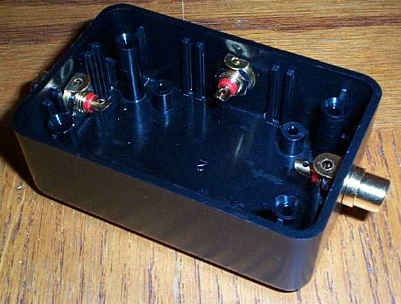
First, drill pilot holes with the small (I used a 3/32″) drill bit in both 2″ panels and one of the 3″ panels of the boxes. Be sure to use the same 3″ side on both boxes for symmetry. Once you’ve gotten them drilled, change to the ¼” bit and enlarge the holes. Make sure to de-burr the holes so the jacks will fit flush and snug. Open the three packages of jacks, and using a pair of pliers, bend all the ground tabs on the ground connection rings to 90 degrees for ease of installation, then install all the red (right) ones in one box and all the white (left) ones in the other. Removal and reinstallation of interconnects will cause the jacks to rotate over time, thereby loosening, shorting, or breaking the connections inside the box. So be sure to install them snuggly.
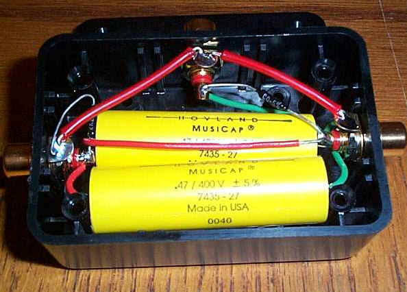
Using your Volt/Ohm Meter, set it to the first resistance setting available that is higher than 2.2 k-ohms, and do some testing on your finished boxes to be sure you’ve made no mistakes. You should see the following readings across these contact points:
1 to 2 – open
3 to 4 – 2.2 k-ohms
5 to 6 – open
2 to 6 – 2.2 k-ohms
2 to 4 – open
1 to 3 – 0 ohms
1 to 5 – 0 ohms
If you get the above readings, it is safe to assume you have assembled the box correctly. If any of them vary, open the box and double check all of your connections. Neither The Stereo Times, nor I , can be held responsible for any damages or problems you may incur as a result of building or implementing this do-it-yourself project. Proceed at YOUR OWN RISK.
Let’s get “meddling”! Insert the interconnects from your preamp’s outputs into the input jacks on both crossover boxes, right to the red-jack box and left to the white-jack box. Install one of the new sets of interconnects from the high-pass output side of both boxes to the respective right and left inputs of the high-frequency amplifier. Finally, install the last set of interconnects from the low-pass output side of both boxes to the respective right and left inputs of the low-frequency amplifier.
Now all you have to do is match the volume levels between the two amps. This can be done by ear, but I would recommend using a Decibel meter and a test disc. You will want to select test tones that are at least one full octave above and below your band pass frequency. For my chosen 120 Hz crossover point, that would mean at least 60 Hz or lower for low-pass side and 240 Hz or higher for the high-pass side. After doing a listening test at a very low volume to be sure that you will not hurt the amps, and to verify that you have done your bench work properly, select a preamp level setting that will approximate your normal listening volume. The reason for this is that the amp-to-amp balance will vary slightly with the volume setting, so you will want to optimize it for your normal listening level.
Set the dB meter on a tripod aimed at your listen area, or rest it on an unobstructed location on your listening seat (atop the seat back for example), and turn it on. Now, run the test tone for the amplifier that does not have variable volume controls and note the SPL reading on your meter. Once you have noted that reference dB level, run the test tone for the other amplifier and, without changing the volume setting on the preamp or moving the SPL meter, adjust the volume controls on the second amplifier until the dB level matches the reference reading obtained from the original amplifier test.
In my system, besides noting an obvious increase in power and extension to the lower frequencies, the mids and highs were presented with a greater level of clarity and detail. Bass runs were clearer, more easily delineated, and downright room-shaking. The soundstage, though exceptionally good before, was somewhat more expansive and a bit better focused. Plus, I could get a little more SOUND PRESSURE out of the rig. When the Genie speaks in Roger Waters’ Amused to Death (Columbia 468761 0), doors rattled in their frames (guess I have more room taming to do)! When the lowest organ note in Saint-Saёns’ Symphony No. 3 (RCA LSC 2340 or Mercury SR 90012) was keyed, my room pressurized akin to the way it feels in the presence of a real pipe organ. Now I am more able to sit comfortably—instead of preparing to dive for the volume control when playing my favorite dynamic pieces at near room-shaking volumes. Not too shabby for less than $50 worth of raw components, some interconnects, and a second amp, eh?
Understand that you may notice subtle voicing changes over the first 20 or 25 hours of use—perhaps even longer. This is common and is due to the final settling of the electronic components and new cables. Now, put on your favorite music, sit back, and enjoy. You’ve earned it!
![]()
Don’t forget to bookmark us! (CTRL-D)
Stereo Times Masthead
Publisher/Founder
Clement Perry
Editor
Dave Thomas
Senior Editors
Frank Alles, Mike Girardi, Russell Lichter, Terry London, Moreno Mitchell, Paul Szabady, Bill Wells, Mike Wright, and Stephen Yan,
Current Contributors
David Abramson, Tim Barrall, Dave Allison, Ron Cook, Lewis Dardick, John Hoffman, Dan Secula, Don Shaulis, Greg Simmons, Eric Teh, Greg Voth, Richard Willie, Ed Van Winkle, Rob Dockery, Richard Doron, and Daveed Turek
Site Management Clement Perry
Ad Designer: Martin Perry



Be the first to comment on: Musical Meddling